
Mechanical winch-pulling concentrates tensile strain at the cable head, limiting outside plant (OSP) fiber runs to under 500 meters when bends are present. Air-Blown Fiber (ABF) jetting overcomes this bottleneck by pairing a synchronized mechanical tractor drive with high-velocity compressed airflow inside an HDPE microduct—suspending the cable on an air cushion and distributing forward shear drag along the entire jacket. This guide breaks down jetting fluid mechanics, compares ASKA’s three machine topologies (Electric Servo-Drive, Pneumatic Microjet, and Handheld Compact), and provides a cross-sectional duct fill calculator and reference table for field crews.
1 Physics of Air-Blown Fiber: Viscous Drag vs. Capstan Friction
In conventional pulling, tension is applied solely at the pulling eye. By the Euler-Eytelwein (Capstan) equation, every conduit sweep multiplies friction exponentially:
For lightweight microcables (1.0 mm to 6.0 mm OD), pulling tension rapidly exceeds the 150 N – 400 N tensile rating, risking fiber strain and micro-bending attenuation. Cable jetting eliminates this by combining mechanical pushing force (Fpush) at the entry tractor with distributed viscous air drag (Fdrag) along every millimeter inside the microduct.
2 Machine Architecture Comparison: Electric vs. Pneumatic vs. Compact
Selecting the right cable blowing machine depends on cable outer diameter, microduct sizing, target span distance, and power availability in the vault or right-of-way. Each of the three primary topologies uses a distinct drive and safety mechanism:
- Millisecond torque auto-stop prevents microcable buckling.
- Digital LCD readout for speed, distance, and push force.
- Low-noise operation suited for urban vaults and campuses.
- Requires battery charging or portable AC/DC power.
- Higher upfront electronics cost than mechanical units.
- 100% pneumatic and weather-resistant for wet, muddy vaults.
- High mechanical torque for trunk cables up to 12.0 mm OD.
- Rated up to 16 bar for long-haul multi-kilometer runs.
- Requires a high-CFM towable air compressor.
- Heavier chassis (14.5 kg) compared to electric/compact units.
- Single-operator portability for ladders, pedestals, and MDUs.
- Pre-set mechanical slip clutch protects delicate drop fibers.
- Under 3-minute setup in tight splice enclosures.
- Limited pushing force for runs beyond 800 meters.
- Restricted to drop/mini-cables ≤ 4.5 mm OD.
3 Technical Comparison Matrix: ASKA Cable Blowing Platforms
Side-by-side parameter comparison across ASKA Communication’s three core microcable blowing platforms:
| Engineering Parameter | Electric Drive Design | Microcable Blowing Machine | Compact Design Machine |
|---|---|---|---|
| Supported Cable OD | 0.8 mm – 6.0 mm | 2.5 mm – 12.0 mm Trunk Ready | 1.0 mm – 4.5 mm |
| Compatible Microduct OD | 3.0 mm – 12.0 mm | 5.0 mm – 20.0 mm | 3.0 mm – 10.0 mm |
| Drive Mechanism | Brushless Electronic Servo | Dual Pneumatic Air Motors | Opposed Pinch-Wheel Drive |
| Max Operating Pressure | 12 bar (175 psi) | 16 bar (232 psi) Max Reach | 10 bar (145 psi) |
| Max Linear Velocity | 100 m/min (330 ft/min) Fastest | 90 m/min (295 ft/min) | 60 m/min (196 ft/min) |
| Buckle & Crush Protection | Closed-Loop Electronic Auto-Stop | Adjustable Pressure Relief Valve | Pre-Set Slip Friction Clutch |
| Unit Chassis Weight | 6.8 kg (15.0 lbs) | 14.5 kg (32.0 lbs) | 4.2 kg (9.2 lbs) Most Portable |
| Telemetry & Metering | Digital LCD (Speed, Distance, Force) | Mechanical Pressure & Trip Gauges | Mechanical Trip Counter |
4 HDPE Microduct Sizing & Fill Ratio Calculation
An out-of-spec Duct Fill Ratio is the leading cause of mid-span jetting stalls. Too tight, and annular airflow is choked; too loose, and air bypasses the cable without generating enough viscous drag to push through bends.
| Microduct Size (OD / ID) | Optimal Cable OD Range | Resulting Area Fill % | Typical Deployment |
|---|---|---|---|
| 7 / 4 mm (4.0 mm ID) | 2.4 mm – 2.8 mm | 36.0% – 49.0% Optimal | FTTH subscriber drops (2F–24F) |
| 10 / 6 mm (6.0 mm ID) | 3.6 mm – 4.2 mm | 36.0% – 49.0% Optimal | FTTx distribution (up to 72F) |
| 12 / 8 mm (8.0 mm ID) | 4.8 mm – 5.6 mm | 36.0% – 49.0% Optimal | Feeder rings & access (up to 144F) |
| 14 / 10 mm (10.0 mm ID) | 6.0 mm – 7.0 mm | 36.0% – 49.0% Optimal | High-count metro trunk (288F–432F) |
5 4-Stage Field Jetting Protocol
To prevent jacket abrasion and reach rated distances up to 2,500 meters, field crews should follow this four-stage commissioning sequence:
6 Featured Equipment: ASKA Cable Blowing & Microduct Lineup
Explore ASKA Communication’s in-stock cable blowing machines, HDPE microducts, and gas-stop fittings from our New Products catalog:
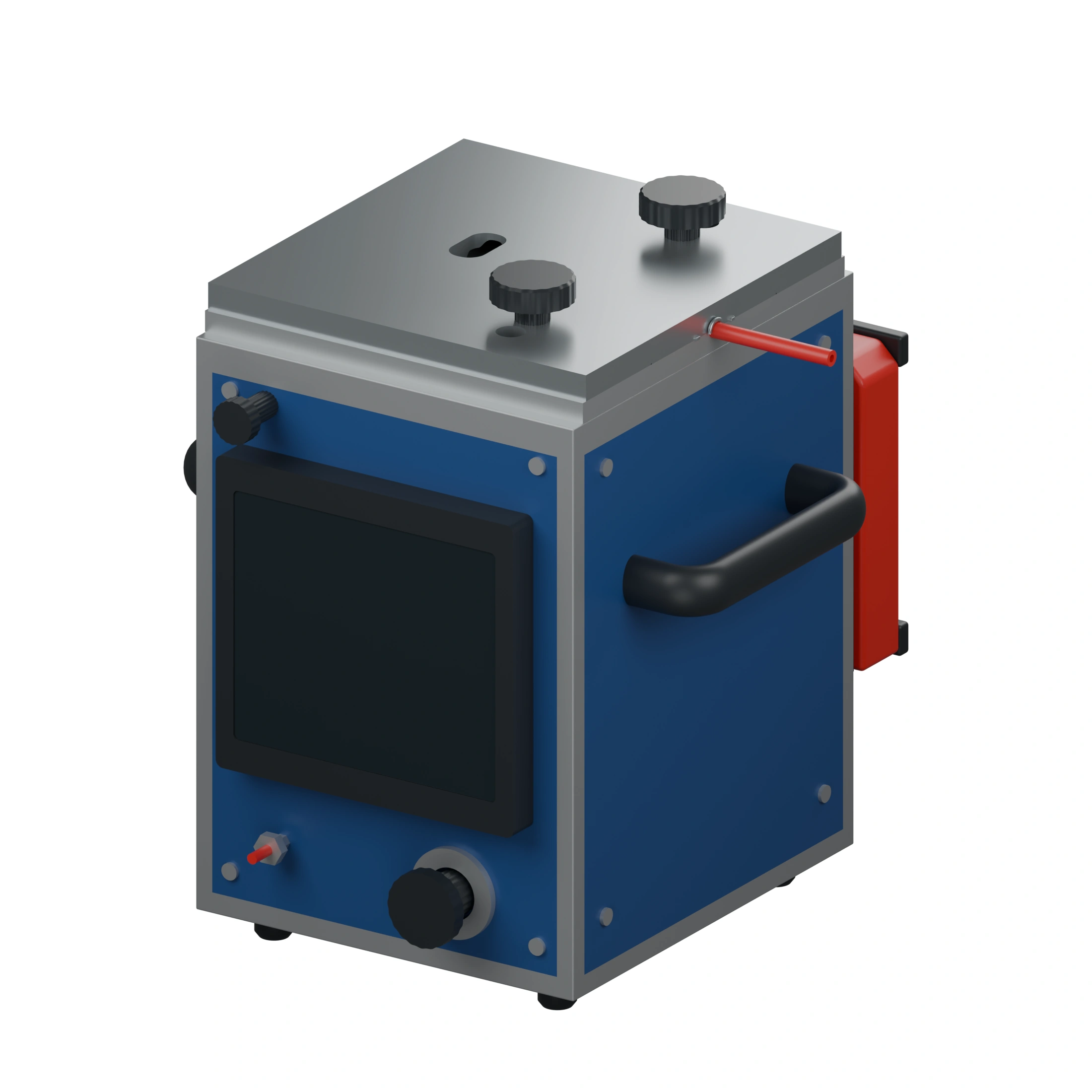
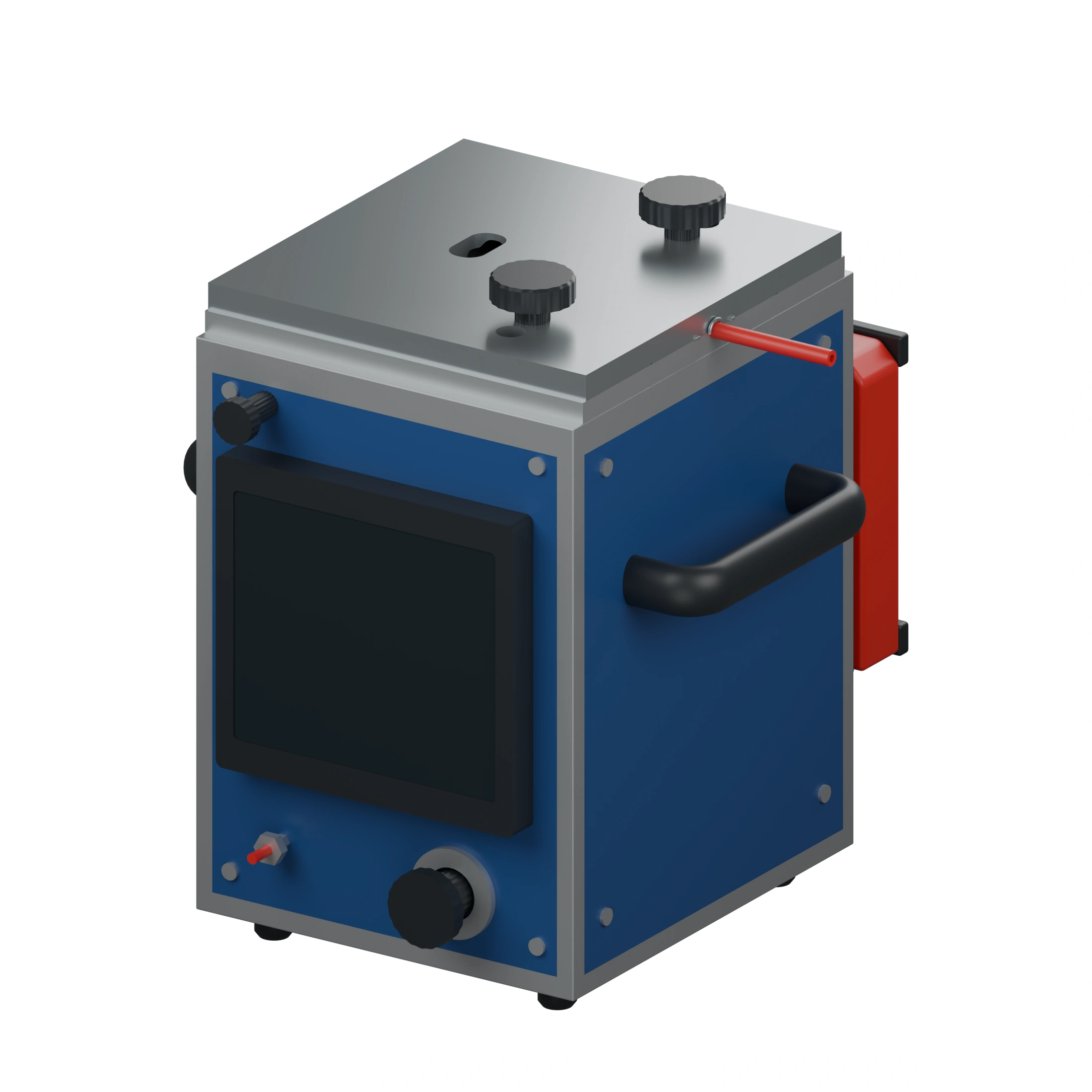
ASKA Cable Blowing Machine — Electric Drive Design
- Cable Range: 0.8 – 6.0 mm
- Microduct: 3.0 – 12.0 mm
- Max Speed: 100 m/min
- Safety: Electronic Auto-Stop
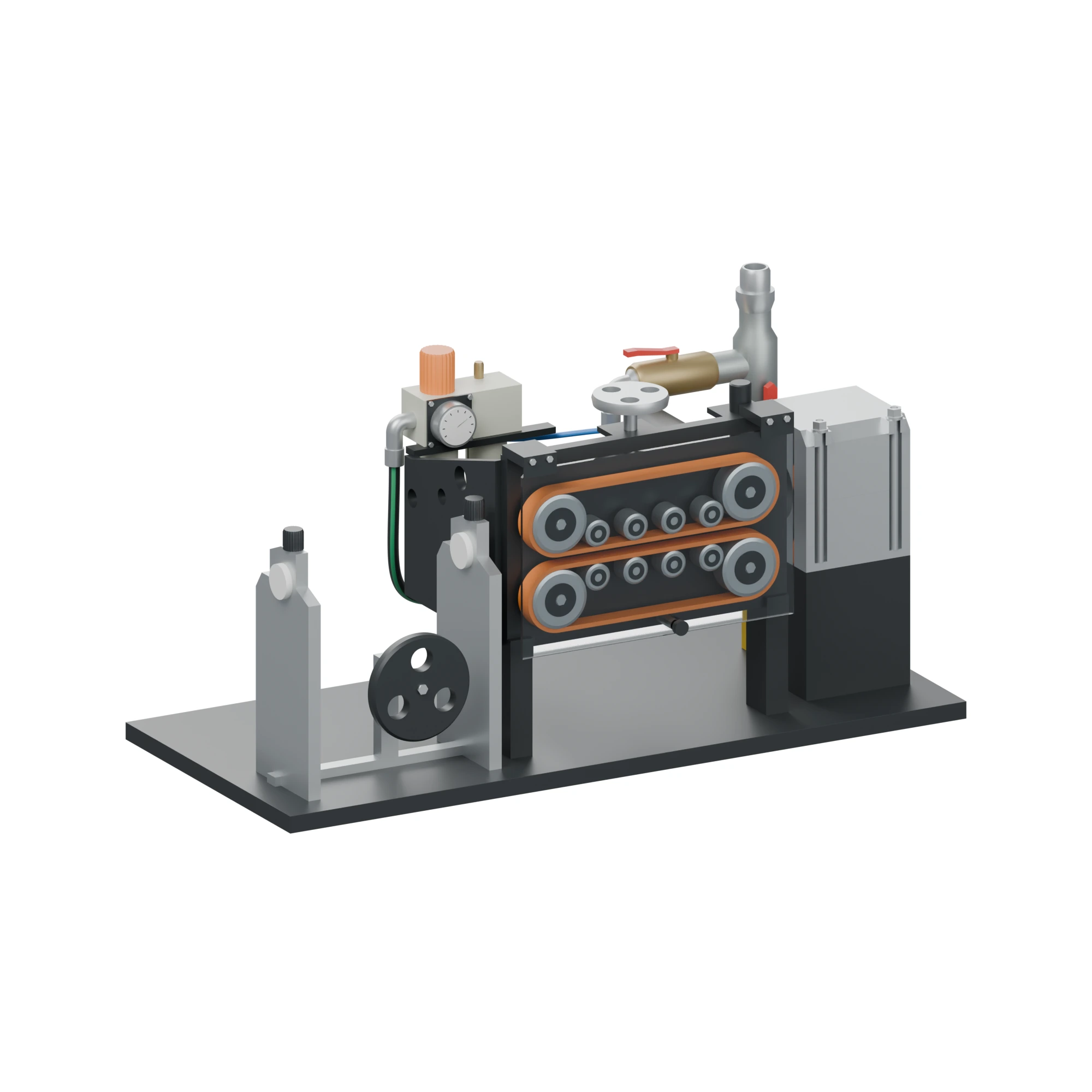
ASKA Microcable Blowing Machine
- Cable Range: 2.5 – 12.0 mm
- Microduct: 5.0 – 20.0 mm
- Max Pressure: 16 bar (232 psi)
- Drive Type: Dual Air Motors
ASKA Cable Blowing Machine — Compact Design
- Unit Weight: 4.2 kg (9.2 lbs)
- Cable Range: 1.0 – 4.5 mm
- Microduct: 3.0 – 10.0 mm
- Deployment: FTTH Drops & MDUs
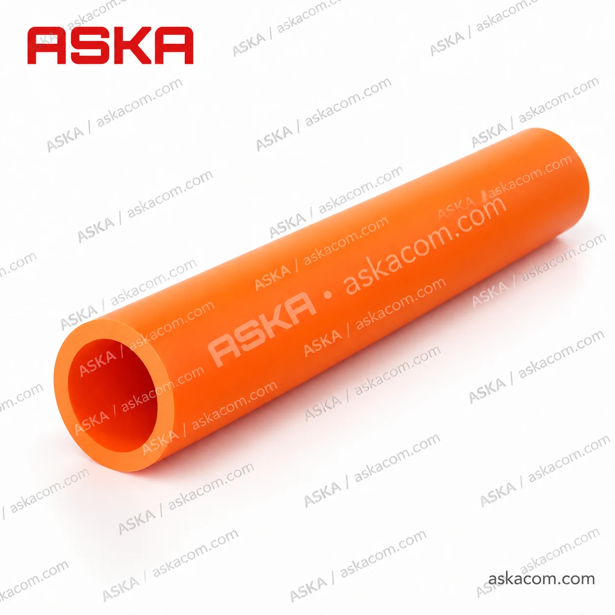
HDPE Individual Microduct — 12/8 mm
- OD / ID: 12.0 / 8.0 mm
- Inner Lining: Low-Friction Ribbed
- Max Pressure: 15 bar Continuous
- Reel Length: 2,000 / 4,000 m
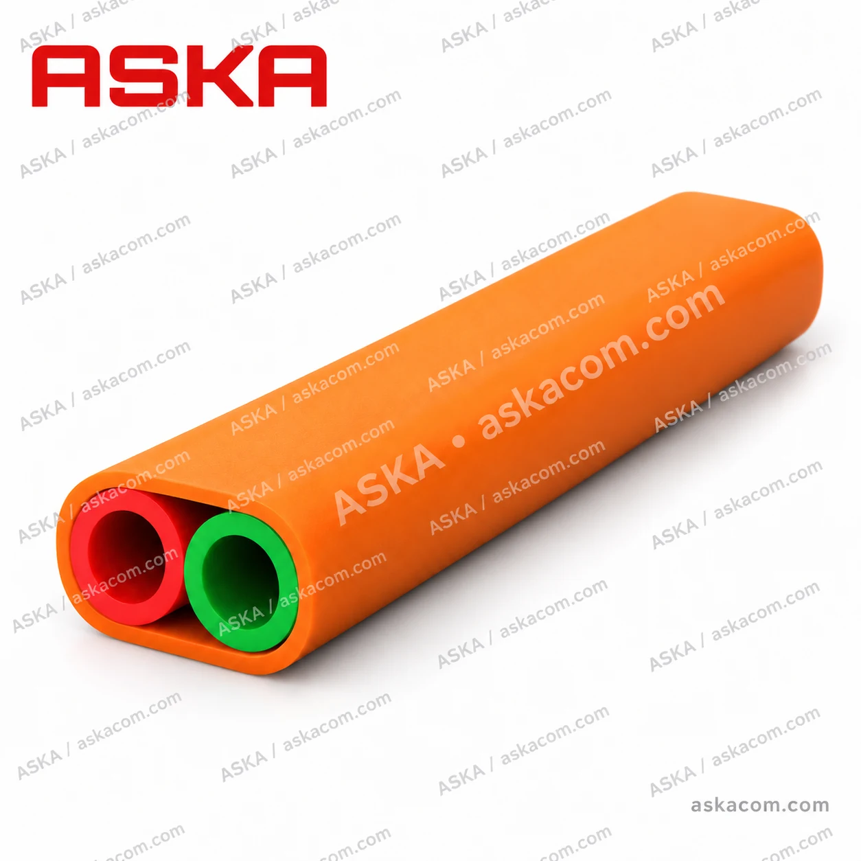
2-Way HDPE Microduct Bundle
- Configuration: 2x Microducts
- Burial Type: Direct Buried (DB)
- Sheath: UV-Stabilized HDPE
- Application: FTTH Feeder Rings
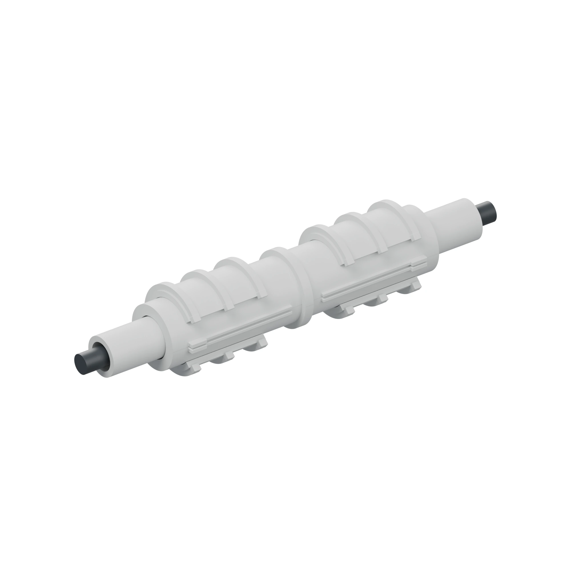
gabocom EBM-GS Split Connector with Gas-Stop
- Sealing Rating: 0.5 bar (7.25 psi)
- Installation: Retrofit (No Cutting)
- Safety: Gas- & Water-Tight
- Body: Transparent Modular
7 Frequently Asked Technical Questions
What air compressor CFM and pressure are required for microcable jetting?
For microducts with inner diameters between 3.5 mm and 8.0 mm, a compressor rated for 10 to 15 bar (145–220 psi) working pressure and 1.0 to 1.5 m³/min (35–53 CFM) airflow is standard. Always route air through an aftercooler and water separator so only dry, oil-free air enters the launch block.
Can microcables be safely blown through pathways with 90° bends?
Yes. Because viscous air drag acts continuously along the entire cable jacket rather than pulling from the nose, microcables glide through sweeping bends without capstan tension buildup—provided bend radii remain at least 15× to 20× the microduct outer diameter.
Why are Gas-Stop connectors required at building and vault entry points?
Underground microducts can channel groundwater and hazardous gases (such as methane or radon) into buildings and active cabinets. Gas-stop split connectors like the gabocom EBM-GS seal the annular gap around live cables without cutting fibers.
Equip Your OSP Crews with High-Speed Jetting Solutions
Contact ASKA Communication for factory-direct B2B pricing, technical datasheets, and fast fulfillment on all cable blowing machines and HDPE microducts.